Ur10 manual
This manual is periodically reviewed and revised.
The ur10 is the biggest in the universal robot cobot series with a load that is up to 10kg. The ur10 manual is the perfect choice for processes like pick and place, palletizing, assembly, packaging etc. With this manual it is very easy to set up with clients reporting on average of half a day. An operator who is not familiar with robot can mount it, unpack the robot and package its first job in less than an hour. The original technology with 3D visualization and intuitive helps the new operators of ur10 to feel incredibly comfortable programming the ur10 robot. What they need to do is to move the robot arm desired positions and simply press the arrow buttons on the screen touch table.
Ur10 manual
.
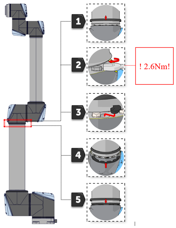
Make sure the washers are fully inserted and flush against the head of the bolt this is important before gently twisting the parts in opposite directions until a mechanical stop is met, ur10 manual. Slide the grey Teflon ring ur10 manual place and gently put the flat ring back on top of the Teflon ring.
.
Table Of Contents. Table of Contents. Quick Links. Universal Robots. Previous Page.
Ur10 manual
The UR10e is our medium duty industrial collaborative robot that combines both long reach and high payload. This cobot will seamlessly integrate into a wide range of applications and delivers endless automation possibilities. Automating repetitive tasks has, from a technology standpoint, never been the challenge. The challenge has been finding the right tool that will enable you to adapt to the future of manufacturing.
Bdsm soumise
Make sure the washers are fully inserted and flush against the head of the bolt this is important before gently twisting the parts in opposite directions until a mechanical stop is met. This information is only for troubleshooting. If it is possible a dual robot calibration kit and second robot of the same model are available and necessary highest possible positional accuracy, and minimal deviation from positions taught prior to joint replacement are required , perform the 3. The kit includes the below parts. If the mentioned parts are not in an acceptable state, rectify immediately. Go to main screen of PolyScope. Check if a URCaps is using this feature as well. Disconnect the main power to the control box. Remove the 4 nuts M6 in the top and bottom of controller module. A MoveP-waypoint were skipped due The value for the blend radius is too large Decrease the blend radius or choose waypoints that are further CA9 to a blend. If more than one Magic file is on USB-stick, they will be run in sequence; the warnings will then appear for each file. Parts and check list The kit includes the below parts. Replace C38A2 the reporting item Address-bus stuck-low test failed Check the log file for what item is reporting this error. To reduce electrical noise in the system 7.
Table Of Contents. Table of Contents.
Red plug with black cable 2. DVI-cable for TP screen 6. Each joint has a unique ID no. Shut down the controller. Enter Low Level Control 3. Replace C38A1 the reporting item Address-bus stuck-high test failed Check the log file for what item is reporting this error. Avoid aborting motions between waypoints with blend Robot has not stopped in the allowed CA4 reaction and braking time Robot program resulted in invalid CA5 setpoint Blending failed and resulted in an Try changing the blend radius or contact technical support CA6 invalid setpoint Target speed does not match target C position Inconsistency between target CA0 position and speed Sanity check failed The software version on the robot must be C the same or later than the version the robot had from the factory. All robots are Dual Robot Calibrated before leaving the factory. Start the robot program in NOreduced speed and verify robot is running as intended. Gently remove black flexible flat ring with a tiny screwdriver or similar tool and twist it around the joint housing. Please refer to chapter 4. Carefully put back the aluminum cover plate, make sure to mount it correct and fix it with the 3 screws Error on 48V powerbus to robot arm Check 48V output from Power supply.


In my opinion the theme is rather interesting. Give with you we will communicate in PM.