Stereo jack socket wiring diagram
One of the most versatile ways to do that is to use a 3.
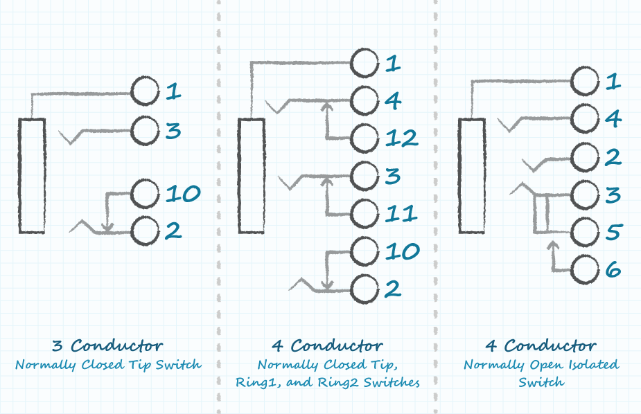
Audio jacks have been around for decades and have been used in a wide variety of applications. While simple in their basic functionality, they can be used in complex systems. To better understand some of their capabilities, we will dig into the "guts" of these connectors and see what they have to offer. When looking at a seemingly simple audio jack datasheet , you will often find an array of schematics with a variation of switches and connections. In this post, we are going to look at how to read these schematics, describe the various switch types available, and discuss how they are implemented in audio applications.
Stereo jack socket wiring diagram
The Jack Plug also called an audio jack, phone plug, stereo plug, mini-jack , is a common audio connector. It is cylindrical in shape with two, three, or four contact points separated by insulating material. Officially the Jack is the socket, but in common parlance the word has come to be used for both types — so make sure that you choose the right one! In the UK, the terms jack plug and jack socket are commonly used for the respectively male and female connectors in order to avoid confusion. The Jack plug was invented for use in telephone switchboards in the 19th century and is still widely used, both in its original 6. The plug types are known by various names. The common descriptive names are derived from the names of the three possible conducting parts of the plug: Tip, Ring, and Sleeve. The modern profile three-conductor jack plug was originally designed for stereo signal connections, with the left channel on the tip, right channel on the ring and common return on the body or sleeve. The tip ring sleeve descriptive names are more common in some English speaking countries than others. In the UK the term stereo jack plug is probably the most common, even for connectors not used to carry stereo signals. The term TRS is particularly appropriate to distinguish these three-conductor stereo plugs used in other than stereo applications. Examples are shown in the table below:. Moulded connectors for computer audio are often colour coded.
Ruel Pereira Pajarion on June 8, at am.
.
The audio jacks was invented in the 19th century for the purpose of use in telephone switchboards and still used widely to transfer analog audio signals. Now-a-days 3. Also, for hobbyists 3. There are different types of 3. These types of audio jacks does not support stereo sound and microphone, which means there is no left and right.
Stereo jack socket wiring diagram
Audio jacks have been around for decades and have been used in a wide variety of applications. While simple in their basic functionality, they can be used in complex systems. To better understand some of their capabilities, we will dig into the "guts" of these connectors and see what they have to offer. When looking at a seemingly simple audio jack datasheet , you will often find an array of schematics with a variation of switches and connections.
Shirt with tuxedo print
MB Ramesh on November 22, at am. What a change to get decent customer service. Ahh , a very good knowledgeful page. I was very impressed with the polite and professional manner in which the issue was dealt with. Most others go left, right, mic, ground. David Blocksidge. One of the most versatile ways to do that is to use a 3. Thaks 4 dygaram. Everything present and correct, and at a lower price than PC World would charge for just one lead! Closed 6. UK: many lines, included in free call packages otherwise charged at the same rate as 01 and 02 numbers. Before soldering or connecting them to anything conductive, run a flame over the wires quickly to burn off the insulation, then wipe clean. In the right cable where the microphone is I find: red, blue and copper wires In the left cable I find: green and copper wires It looks likely that the green and red are left and right audio respectively like in your photo of a standard, 1-cable TTRS. Going to connect a wired 3.
A TRS connector tip, ring, sleeve also called an audio jack, phone jack, phone plug, jack plug, stereo plug, mini-jack, mini-stereo, or headphone jack , is a common analog audio connector. It is cylindrical in shape, typically with three contacts, although sometimes with two a TS connector or four a TRRS connector. The connector's name is derived from the names of three conducting parts of the plug: Tip , Ring , and Sleeve.
Anon on February 19, at am. What a change to get decent customer service. If you only need a mono audio input with the TRRS connector, you can combine the combine the red and green wires to make a single mono audio wire, then combine the ground wires to make a single ground wire. Fantastic help and service. Example of a mated audio jack and plug Now, we are going to add a switch to the terminal 2 position tip. David Blocksidge. Now again, we visualize the mating plug being inserted from left to right. Leads Direct makes great efforts to provide accurate and complete information. John Dockery-Jackson on December 2, at am. Below are some typical schematics that show some of those switching options. Ahmed on April 22, at am. I will recommend you to others Ian Think Marketing Material. Matt Dunn. Great article around a common set of problems with evolving tech. But the feather in your cap was the excellent service yesterday when at pm, despite believing the deliveries had already been picked up, your sales representative went and checked, just to make sure.


0 thoughts on “Stereo jack socket wiring diagram”