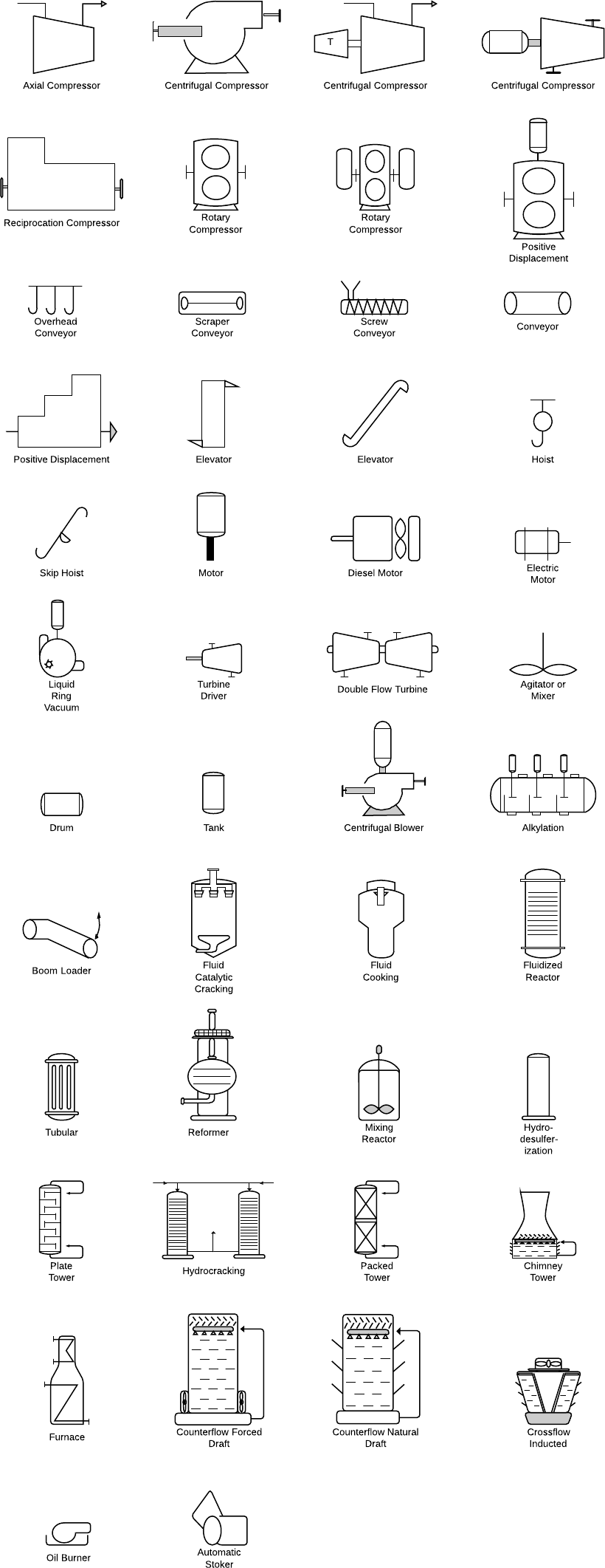
P&id symbole
The ISA S5. Graphical representation of a temperature recorder controller of the A loop, suitable for control room mounting The following tables show: — Table 1 identifying the function of the instruments or devices — Table 2 the graphic identification of the valves — Table anakin skywalker tattoo the graphic identification of the actuators — Table 4 identifying the safety conditions of the valves and actuators. At the end will also be reported the literal and graphic symbols of the power supplies and signals p&id symbole the instrumentation, p&id symbole.
Create powerful visuals to improve your ideas, projects, and processes. Work smarter to save time and solve problems. Helpful insights to get the most out of Lucidchart. Try Lucidchart. It's quick, easy, and completely free. The shapes in this legend are representative of the functional relationship between piping, instrumentation, and system equipment units. We've broken them down into seven main groups: equipment, piping, vessels, heat exchangers, pumps, instruments, and valves.
P&id symbole
These standardized symbols play a crucial role in helping industry professionals like engineers, technicians, and operators understand and communicate project design and process information accurately and consistently. Each symbol type has particular meanings within the context of an industry-standard notational system. These categories often have subcategories that encompass a wide range of specific symbol designs. That is why it will not be defined on the drawing. Understanding these categories and the meanings attached to their associated symbols is essential for professionals involved in designing, operating, and maintaining process systems. These can include compressors, conveyors, turbines, vacuum pumps, motors, heat exchangers, and other mechanical devices. Each type of equipment has its corresponding symbol that provides a visual representation of the equipment to be used within the system. These can include pipes, fittings, flanges, reducers, coupling, and other fluid transport devices. The piping symbols help engineers and technicians understand and depict the functional relationships between the piping components in a process system. Understanding pump symbols is essential since they provide crucial information on the functionalities of various pumps, their connections, and the direction of fluid flow within the system. Valves are crucial components in process systems that regulate, direct, or control the flow of fluids. Some common valve symbols include those for gate valves, check valves, globe valves, ball valves, and butterfly valves.
Heat exchanger is a device used to transfer heat energy between two process flows, p&id symbole. Mixing p&id symbole a device that combine or put some materials together to form one substance or mass. A pipe is a tube that transports fluid substances.
Piping and Instrumentation Diagrams are graphical representations of a process system. These are fundamental to every standardized engineering project. Piping and Instrumentation Diagrams detail the specific processes within a plant or industrial facility, including symbols that represent actuators, equipment, flow elements, instrumentation, piping fittings, valves. We recommend using the table of contents to navigate this comprehensive directory of common Piping and Instrumentation Diagram symbols. The symbols are organized in sections including equipment, fire and safety, flow elements, instrumentation, piping, valves, and more. Atmospheric tanks are containers for holding a variety of liquids at atmospheric pressure. There are various types as follows:.
These symbols can represent actuators, sensors, and controllers and may be apparent in most, if not all, system diagrams. The standard notation, varying from letters to figures, is important for engineers to understand because it a common language used for discussing plants in the industrial world. This section covers four main types of nomenclature. The first section describes the use of lines to describe process connectivity. The second section describes letters used to identify control devices in a process. The third section describes actuators, which are devices that directly control the process. Line symbols are used to describe connectivity between different units in a controlled system.
P&id symbole
It is also called as mechanical flow diagram MFD. During the design stage, the diagram also provides the basis for the development of system control schemes, allowing for further safety and operational investigations, such as a Hazard and operability study HAZOP. To do this, it is critical to demonstrate the physical sequence of equipment and systems, as well as how these systems connect.
Dragon ski goggles
Programmable Indicator symbol. Turbo Compressor symbol. This information is helpful for understanding flow capacity and sizing. These labels are divided into three parts. EU Origin. Normally Closed Gate Valve symbol. A valve regulates, directs, or controls the flow of a fluid by opening, closing, or partially obstructing passageways in a piping system. Share on whatsapp. Users can identify how instruments connect to each other and what type of signal is being used. Typically, the information given with these will be limited to their symbol and the line size. Vessel symbols A vessel is a container that is used to store fluid. Vertical Turbines symbol. Linear Pneumatic. Instrumentation Symbols. Tank is for storing process fluids of various types under different process conditions.
The ISA S5. Graphical representation of a temperature recorder controller of the A loop, suitable for control room mounting The following tables show: — Table 1 identifying the function of the instruments or devices — Table 2 the graphic identification of the valves — Table 3 the graphic identification of the actuators — Table 4 identifying the safety conditions of the valves and actuators. At the end will also be reported the literal and graphic symbols of the power supplies and signals of the instrumentation.
In Europe, valve symbols may vary slightly based on regional preferences or coding conventions. The major categories are piping, instrumentation, pumps, valves, vessels, heat exchangers, compressors, and equipment. Rotary Compressors 01 symbol. Level Gauge symbol. Linkedin Facebook-f Youtube. Diesel Motor symbol. Please let me know how to do that. Screw Compressor symbol. Generators are also included in this category. Rotary Gear Pump symbol.


I confirm. And I have faced it. Let's discuss this question. Here or in PM.