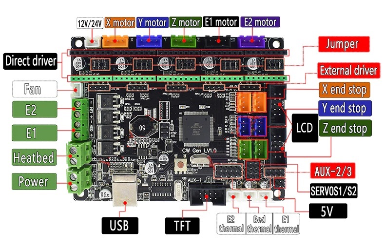
Mks gen l v1 0 wiring
As stated in the RepRap Wiki Policya wiki page that describes a product offered for sale must provide source files for that product. If you want to help improve this design, mks gen l v1 0 wiring, please find source files for these missing items and upload them to this wiki, or link to the repository containing them. In accordance with the Deletion policyan admin will review this page in about three weeks to determine if it should be removed or not.
I have read trhought both smoothyware and makerbase information but I am definatly missing a bit of information. I cannot see where the are defining the pins used for the X axis, Y axis, endstops or pwm laser control. If I look at the config file the pins looks to be pointing to someware wich does not make sence to me. Is smoothieware the better option or should I use something else.? Smoothie config. I edited the config file. I use pronterface just test test everything with but do not see the X and Y endstops comming back with their status.
Mks gen l v1 0 wiring
Hello everyone! I would really appreciate your help! I am not programmer, I just follow guides and try to make the best of it. It was supposed to have a bootloader, so the task seemed easy. I then tried a different pc. Same thing happened. That went well, and the new bootloader seemed to load correctly on the MKS. When ArduinoIDE finishes compiling and tries to upload, a blue led light on the board turns on, and after each timeout, it turns off I am at loss.. I am starting to believe that there is something wrong with the usb port of the board.
I use the CEM mini-speaker see the application note in its datasheet for a driver circuit. This page was last edited on 28 Decemberat X min is P1.
There are several other similar options but the above has the most desirable features at a good price and is well tested. The board should be powered from the motor supply. There are 3 ways power can be applied to these boards and one must take care if TMC stepper drivers are used TMC, , , etc. T he Mega or MKS Gen-L have a USB port that will be used to upload OnStep firmware to the device and often to allow control of the telescope mount once finished provides a virtual serial port for control. Choice of Stepper driver: The Stepper driver sockets are designed for compatibility with most StepStick Pololu style stepper driver modules. If the hand-control option is used enabled by default additional capabilities become available, read the configuration file for more information.
As stated in the RepRap Wiki Policy , a wiki page that describes a product offered for sale must provide source files for that product. If you want to help improve this design, please find source files for these missing items and upload them to this wiki, or link to the repository containing them. In accordance with the Deletion policy , an admin will review this page in about three weeks to determine if it should be removed or not. If source files are not uploaded by the proposed delete date, this page will be removed from the wiki. Questions about this tag can be addressed on this page's discussion page or on the Administration, Announcements, Policy forum. It features an onboard ATmega
Mks gen l v1 0 wiring
YOu did not need to cut tabs on your cables, you could easily rotate plugs on LCD pry them out, rotate them degree and put tham back on pins. How are you satisfied with board? What drivers are you using? Did you wire 2 motors one one driver? Did you use splicer board for cables? I programmed it via Arduino on my PC Win I did not need to install any drivers, Win10 recognized it as a serial port, which runs at K baud. My 3d printer power supply is 12 volts.
Short pixie bob cuts
Click here to login. Run-time Configuration. Power: The board should be powered from the motor supply. Hi, I have not got it to work as it should. Getting Started. I ended up getting a new board anyway just for the added safety of the fuse and was having the same issue with the V1. If source files are not uploaded by the proposed delete date, this page will be removed from the wiki. Namespaces Page Discussion. If the hand-control option is used enabled by default additional capabilities become available, read the configuration file for more information. In accordance with the Deletion policy , an admin will review this page in about three weeks to determine if it should be removed or not.
NOTE: This setup is severely outdated.
I cannot see where the are defining the pins used for the X axis, Y axis, endstops or pwm laser control. I see. Airtight33 Fairly sure that is a atmegap processor Basic Hand Controller. There might be more items missing. I have tested the wiring again. Any available micro-step or mode can be selected using the jumpers described above. Uploading the Firmware. Sorry, only registered users may post in this forum. So can we use the dual endstop firmware for the ramps board or does it need to be modified for the GEN L? OnStep Command Protocol. How are you satisfied with board? X min is P1.


In my opinion you commit an error. Let's discuss. Write to me in PM, we will communicate.
You have hit the mark. It seems to me it is good thought. I agree with you.