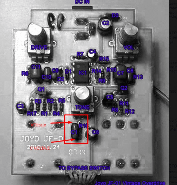
Joyo vintage overdrive schematic
Hello David i have a cuestion, i need replaced de Capacitor 10? Hello, good question, It's not weel explained in my post above.
By fishingjude October 16, in Effects and Processors. First off - Why are your changing the switch? The one that comes with the pedal is a true bypass. If its failing, have you cleaned it with pot cleaner first? If it hasn't failed yet there's absolutely nothing to be gained by changing it. If it has failed and cleaning hasn't fixed it then you simply need to buy another switch of the same kind, de-solder the old one and re-solder the new one in its place.
Joyo vintage overdrive schematic
By ColinB , July 14, in Effects. I found this scematic for the TS-5 online, and and then worked out which componants were mapped to which by following the traces on the JF I removed the equivalent diodes D2 and D3, the resistors R18 and R19, and the capacitor C10 from the Joyo circuit board. Here they're labelled up as they would be according to the TS-5 schematic: So I replaced R19 with a 10k ohm resistor, R18 with a 3. I had to solder in the capacitor on the underneath of the board due to size - but there's plenty of space to do that. This makes it so much more useable as a drive pedal on bass. C10 allows more bass through, R18 and 19 allow the drive to be turned right down so the pedal can be used as a clean boost if so required, and the diode combination sound great. That looks very very promising!!! I have one of those but I'm not using it for bass because despite how nice it sounds, it just cuts too much low end for me to be able to use it unless it's permanently on and compensate with the amp controls I wish I were better with my hands for these sort of minute modifications as I'd love to make the Joyo useable for bass Maybe one day I'll summon the courage needed! Not complaining, as it sounds lovely for guitar! Maybe part of the "tightening" the sound it does is through cutting some of the "flab".
I did an initial low volume test.
Welcome, Guest. Please login or register. Home Help Search Login Register. Pages: [ 1 ] Go Down. One more! So it's on the way.
Post by Mondoslug » 06 Jul , Post by Hides-His-Eyes » 06 Jul , Post by culturejam » 06 Jul , Post by reddo » 06 Jul , Post by greeny23 » 06 Jul , Post by lolbou » 06 Jul ,
Joyo vintage overdrive schematic
Hello David i have a cuestion, i need replaced de Capacitor 10? Hello, good question, It's not weel explained in my post above. Anyway, the fat switch select from the C10 cap between a nF or nF, but you can experiment other values that may sounds better to you. Hallo,if you can know how much the value of C2 and DO, less clear writing. Hello, D0 is a 1n it's just a reverse current protection diode, C2 is uF. My question is how do I know which one of the wires are the pc in and the pc out coming from the pcb board of the pedal. I need to connect these 2 wires to the new relay module but I cant see anything showing them marked on the pedal. Thanks in advance. I am new to this but I am eager to learn.
Morrita por dinero
Bottom line is it sounds a whole lot better than the Morley Distortion I pulled off of that pedalboard tonight. If not then let this be the standard for all net communications regarding pot setting from now on out! Got any ideas what to do. It is just a genuinely good pedal and it just so happens that it can be picked up for a very reasonable amount of money. First off - Why are your changing the switch? I've learned not to fully trust bedroom level test. Not messing with you. It is a good pedal platform. Kind of a blatting blocking distortion, ripped speaker, bad tubes - sound. All and all it's a good pedal, its got it's own personality and like any tool, you have learn the best way to use it. The tone control is really responsive and covers a wide spectrum from dark to really bright.
All user manuals are available to download in English for the UK, these are the original technical specs as supplied in the JOYO guitar effect box. Your Cart.
Thank you Steve. Contact us. It really don't make a whole lot of difference, you turn your knob until it sounds good and stop. Using only the Drive and Tone knobs, you can get a nice sweet crunch out of a clean channel, and the volume knob can be used by itself to provide a relatively transparent clean boost. In my little world my way makes sense to me but that puts my reference off from yours. One more! Post by lolbou » 06 Jul , Dadocaster said:. Recommended Posts. Post by Ben N » 07 Jul , I like it! I found this scematic for the TS-5 online, and and then worked out which componants were mapped to which by following the traces on the JF I removed the equivalent diodes D2 and D3, the resistors R18 and R19, and the capacitor C10 from the Joyo circuit board. Post by greeny23 » 06 Jul , Do not drink and solder. Tube Amp Schematics library.


I join told all above. Let's discuss this question.
It is the valuable answer
Moscow was under construction not at once.