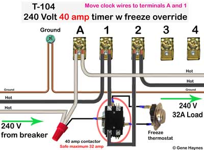
Intermatic timer wiring diagram
Forgot your Password? We welcome your comments and suggestions.
Log in. Sign up. Home Forums Home Improvement Electrical. JavaScript is disabled. For a better experience, please enable JavaScript in your browser before proceeding. Not convenient. As my pool has two infinity edges, it needs to have the pump running when laps are being swum.
Intermatic timer wiring diagram
Log in. Sign up. Jump to Latest Follow. JavaScript is disabled. For a better experience, please enable JavaScript in your browser before proceeding. Joined Dec 21, I just hope I can figure out what to do when putting a 3-way switch into the 4-way outlet. Joined Mar 13, That will work IF the light and power connection is in the same box. You haven't answered the question of how the current switches are wired. If power comes in at one three way and light is connected to second three way then you need a fourth wire. Joined Jan 7, It's critical that you answer Joed. His question determines where the timer is located.
Add tape to white wire, when using black-and-white wires for Volt, This will notify next electrician that white wire carries power.
Running pool equipment 24 hours is usually unnecessary and expensive. Installing an Intermatic T timer is a great way to dramatically reduce run time and energy costs. The following steps will provide a guide on how to install the T timer. Note, timers vary with supply voltage. A T timer is used for V supply voltage.
Running pool equipment 24 hours is usually unnecessary and expensive. Installing an Intermatic T timer is a great way to dramatically reduce run time and energy costs. The following steps will provide a guide on how to install the T timer. Note, timers vary with supply voltage. A T timer is used for V supply voltage. If you are using V supply voltage, you will need a T timer. The installation steps are the same for either. Toggle navigation Menu Cart My Account. Expert Advice: Chat Now or Call Hassle-Free Returns.
Intermatic timer wiring diagram
Hide thumbs. Quick Links. Enlarged version. Troubleshooting Guide Observed Problem. The time of day or timer settings have not. Switch timer is in RANDom mode, which var-. The Astronomic and Specific switching times. For example, you've set ON to. Switch timer switches at incorrect times.
Ritu pandey
Step 30 Turn on the the power at the breaker panel. Use only volt wire. Lamp cord, extension cords are not rated volt. Is clock motor WG? I do not know how to upload drawings here, so in the meantime, you can request I send it to your email. It only matters that one cable is on 1 and the other is on 3. We could probably be clearer on how this timer is going to be used. T with Metal Enclosure. This means the T will toggle the pump between high and low speed. Is clock motor WG? I just hope I can figure out what to do when putting a 3-way switch into the 4-way outlet. Find all posts by HandyRon. Can I just use one of the v legs coming into the box, but where would my neutral wire go?
.
This is a V timer. Expert Advice: Chat Now or Call I'm under the impression you don't have or know how to use a voltage tester. Once you've enabled Javascript, please refresh this page. Make sure of that before you start disconnecting things. The wiring instructions state- "This time switch can be wired to control two circuits as Single Pole Double Throw, or to control one circuit as Single Pole Single Throw. It's possible it was inadvertently moved, causing it to kick off at the incorrect time. Thanks, but. Close the timer door and enjoy the energy savings with using a timer. You haven't answered the question of how the current switches are wired. The "On" tripper is typically green and will be labeled "On". Step 22 The next steps will involve programming the timer. Nealtw Replies.


I do not believe.
Today I was specially registered at a forum to participate in discussion of this question.