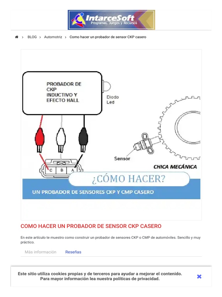
Diagrama sensor ckp 3 cables
La funcin que cumple es la de ubicar la posicin del cigeal Pistn 1 y el cambio de velocidad del giro del cigeal o RPM del motor, con el objetivo de que el PCM controle la activacin del rel de la bomba de combustible, la dosificacin de combustible y el punto de encendido, diagrama sensor ckp 3 cables. Este sensor puede ser de tipo inductivo, efecto hall o ptico.
Es un sensor de tipo inductivo, tambin existe de efecto hall. Su constitucin puede ser d un generador de imn permanente en el cual no se necesita alimentacin elctrica, o de reluctancia variable en el cual si se necesita alimentacin elctrica. Su funcin es detectar las variaciones de campo magntico cuando se producen los cambios de posicin del cigeal. El sensor provee informacin de la unidad electrnica de control sobre la posicin del cigeal y las RPM del motor, y produce un voltaje alterno sinusoidal de frecuencia y amplitud variable. Figura 1. Sensor CKP Inductivo.
Diagrama sensor ckp 3 cables
Log in. Sign up. Home Forums Prelude Forums 5th Gen. JavaScript is disabled. For a better experience, please enable JavaScript in your browser before proceeding. There's four wires, and my Chilton's doesn't say which wires go to what sensor. I want to test it to see if it's giving me my CEL. Sort by Oldest first Oldest first Newest first Most reactions. When you buy a new CKP sensor, the TDC sensor should be attached as well and the wiring is only long enough for them to go into the right spots. I can't follow the wires because they're hidden behind the lower timing cover. All I can do is disconnect the connector below the brake master cylinder and poke around with a multimeter. Pictures would help. I just need to know what color wires go to the tdc sensor.
Descargar ahora.
Hola, soy nuevo en este foro y necesito que me iluminen un poco. Soy profesor de informatica, apasionado de los motores de combustion y la electronica, esto ultimo no es mi fuerte, pero tengo muchas ganas de aprender. Hace unos meses empece a usar arduino me parecio muy interesante sobre todo la forma de programar muy entendible ya que se fundamenta en el lenguaje C. Quiero montarlo en una rueda dentada para encender un led cada vez que pasa por un diente de la rueda, posterior mente usarlo para contar las revoluciones de un motor. Si podrian darle alguna idea de como hacerlo, estaria muy agradecido.
A crank sensor CKP [1] [2] [3] is an electronic device used in an internal combustion engine , both petrol and diesel, to monitor the position or rotational speed of the crankshaft. This information is used by engine management systems to control the fuel injection or the ignition system timing and other engine parameters. Before electronic crank sensors were available, the distributor would have to be manually adjusted to a timing mark on petrol engines. The crank sensor can be used in combination with a similar camshaft position sensor CMP [4] [5] [3] to monitor the relationship between the pistons and valves in the engine, which is particularly important in engines with variable valve timing. This method is also used to "synchronise" a four stroke engine upon starting, allowing the management system to know when to inject the fuel.
Diagrama sensor ckp 3 cables
The crankshaft position sensor is an electronic sensor that measures the position of the crankshaft. There are two most common types of crankshaft position sensors that are used commonly in the car. One is the inductive coil pick-up crank sensor, which produces an alternating current in the coil and the other is the Hall-effect crank sensor. The Hall-effect crankshaft sensor generates the digital square wave signal and sends it to the ECU of the car. Most modern cars use the Hall-effect crankshaft sensors because of their more accurate readings. The inductive pick-up coil sensors have two wires whereas the Hall-effect sensors have three wires. A Crankshaft Position Sensor CKP is an electronic device used in an internal combustion engine, both petrol and diesel, to monitor the position or rotational speed of the crankshaft.
Occitan flag
Medicin del aislamiento a masa: Conectar el hmetro a un pin del sensor y el otro pin a masa. Sensor CKP ptico Fuente: mecanicabasica. Hola, disculpenme creo que no me dejo entender, en el hilo 5 hice mencion sobre el sensor de efecto hall nada mas eso. Marco Teorico Marco Teorico. Cuestionario Autotronica Cuestionario Autotronica. Consta de una bobina arrollada sobre un ncleo de imn, enfrentado a la rueda dentada o fnica. Algo que tendras que armar. Recommended Communities. Sensores Sensores. Este al igual que el de efecto Hall posee tres cables uno de alimentacin, uno de tierra y el restante es de seal. Verificar la tensin de alimentacin y la variacin de la tensin de la seal de salida Comprobar la seal con un osciloscopio. Top Contributors this Month View All. Razonamiento Abstracto Razonamiento Abstracto. Please consider creating a new thread.
.
Hi, Si no quires hacerlo con componentes aqui adjunto un link de uno que no tienes que hacer nada. Nte Inen 2 - Nte Inen 2 - Generador de Pulso Generador de Pulso. Tabla de resistencias del sensor CKP. There's four wires, and my Chilton's doesn't say which wires go to what sensor. Hola, disculpenme creo que no me dejo entender, en el hilo 5 hice mencion sobre el sensor de efecto hall nada mas eso. Cuentavueltas y sensor inductivo Hardware. I want to test it to see if it's giving me my CEL. Test Secuencias Test Secuencias. Surbyte September 6, , am 4.


In my opinion you are not right. I am assured. I can defend the position. Write to me in PM, we will discuss.
Excuse for that I interfere � here recently. But this theme is very close to me. Is ready to help.